Hacking an Old Red Landline Phone with Arduino
So we've had this two-week long “Extended 7x7 Project” for Major Studio 1 and I decided to continue working on my old red, landline phone. The main objective of this project was to do a physical exploration of an antiquated object and see how we could reuse the same components to create or invent something new. In other words, it is also known as the act of repurposing an object.

As explained previously, the phone is divided into two main units called “Base” and “Headset” — both are connected with a spiral, red wire. The headset consists of an earpiece acting as an internal sound receiver, a mouthpiece or microphone, and a 15-button keypad or dialer. The latter seems to be the most feasible component for repurposing because it allows a custom input generation that opens up to a greater possibility of output modification.
In summary, I am going to focus on hacking the keypad from the old phone and will then turn it into a jukebox player. The way it will work is the keypad will be specifically programmed to become a custom input for my Arduino micro-controller board. Each key on the keypad will produce a different musical note or an 8-bit song, depending on the key that is being pressed.
DESIGN PROCESS

Mind mapping of how I look at the entire project: Possible Inputs vs Possible Outputs.
Since this is my first project that involves physical computing, I have spent most of my time researching and learning the basics. I first made a mind-mapping that lists down all the challenges, possible inputs in case I couldn't get the original phone keypad to work, and also the possible outputs.
POSSIBLE INPUTS


Another alternative inputs in case I could not get my phone's keypad to work:
Left: 4x3 Matrix 12-Key Array Membrane Switch Keypad Keyboard
Right: 4x4 Universial 16 Key Switch Keypad Keyboard For Arduino
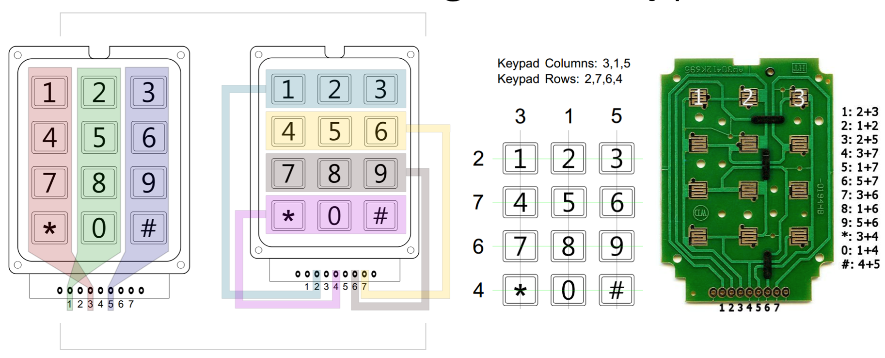
Understanding 4x3 keypad. Images from Sparkfun's Datasheet.
At early stage, a lot of experiments have been done to get a basic understanding of how keypad works as an input. I did a comparison of Sparkfun’s 12-button keypad and the 4x3 matrix Universal 16-key Switch Keypad for Arduino, both of which have 7 pin connectors and tons of tutorials online. I tried setting up one by one and spend hours on them, yet somehow the Sparkfun keypad felt a bit clunky because it gives different unstable result. See the video below, I don't know what was wrong but it doesn't recognize key 6, 7, and 8:
HACKING THE ORIGINAL PHONE KEYPAD
It felt like there were so many challenges since the very beginning of this project. After playing around with Sparkfun's keyboard I realized that those keypad has 7 pins, but my phone's Keypad has 11 pins instead - which makes it trickier to figure out which pin goes to which PWM digital pin on Arduino.
So yeah, I spend days and days trying to figure out how to solve the problem. And also, some of the connector cables were pretty old and clunky, so I had to desolder and replace them with new wires to make sure the connection gets more stable. It's been a real challenge asking people and researching how to carefully identify and break down all of the phone components, how to detach the built-in phone keypad from its circuit board, and even learning basic soldering/ desoldering technique, etc.
BTW, you can see what my first soldering looks like. It's so ugly hahaha but I enjoyed it though.

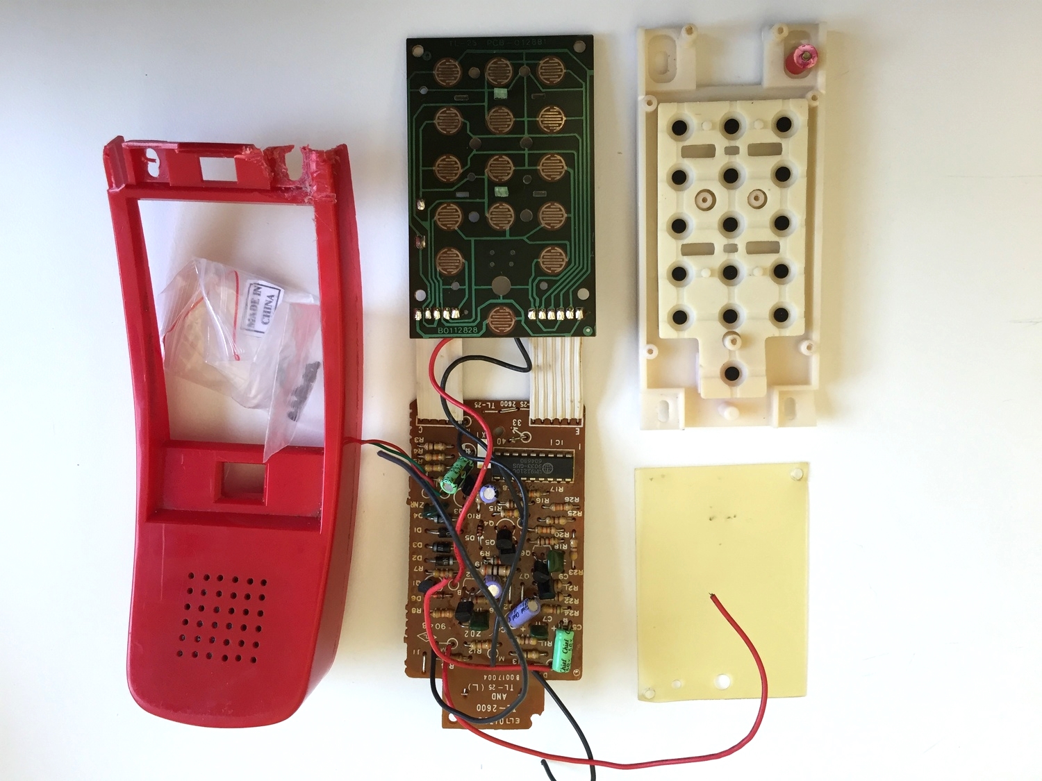

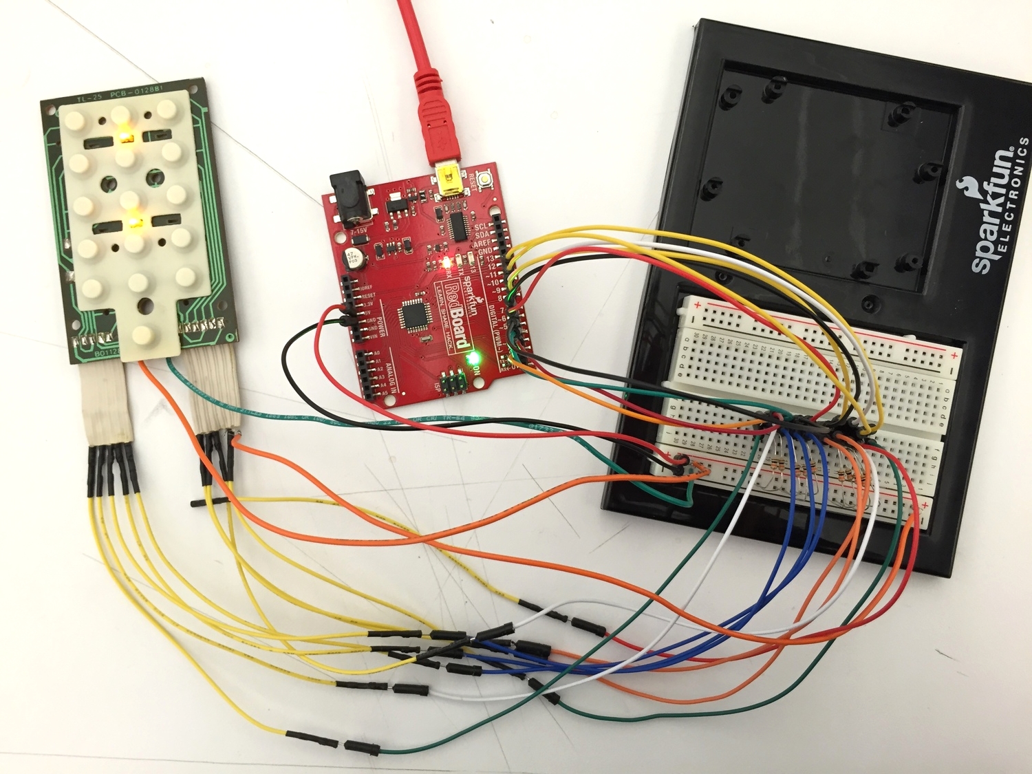
My first ever attempt at desoldering, and how my phone's keypad looked like when connected to a redboard.
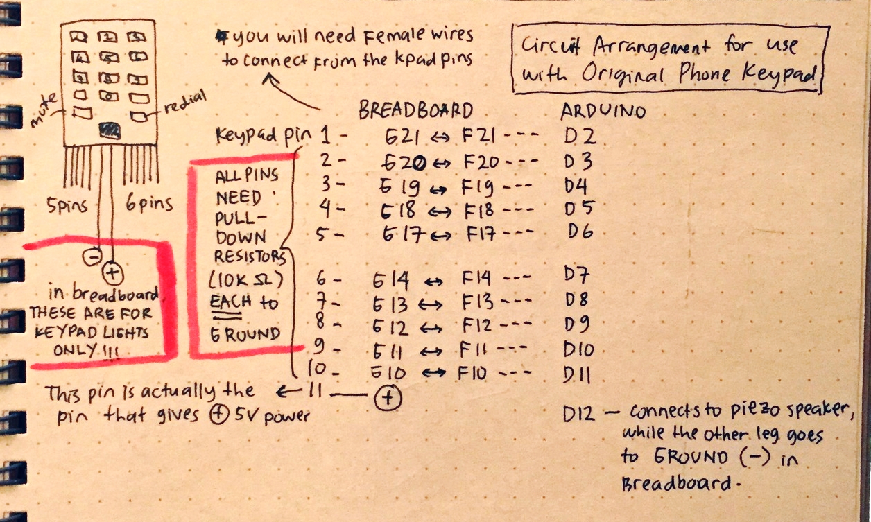
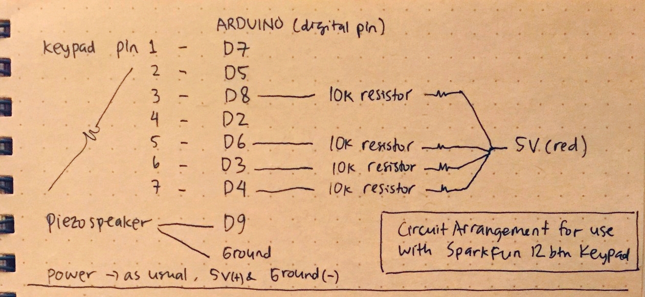
And here's the wiring scheme.
POSSIBLE OUTPUTS
I’ve also played around with possible outputs before I made a decision to turn the keypads into a jukebox player. It includes connecting the LCD screen to the keypad to make some sort of calculator, and making an adjustable LED board game that uses the keypad as the main controller.
After conducting a few experiments, I came to realize that those outputs aren’t possible due to lack of PWM digital pins on my Arduino board. Since the keypad already occupied so many pin spaces, the solution for this problem is quite complex: either I need to figure out how to convert analog to digital pins, or use two Arduino boards and make a bigger circuit. Due to time constraints, I decided to stick with having Piezo speaker as the main output that plays a musical note correlating to each key being pressed. That way, the output is no longer an issue and I only need to focus on getting my input done.
FINAL RESULT
So yeah, I finally made it work using my original phone's keypad! It seems pretty simple but trust me, it was a lot of headache for first timers, lol. Cheers!