7x7 Day 5: Physical Exploration of An Old Telephone
So today my roommate gave me an old unused landline telephone and she said that I can play around with it. And so I did. I have never once in my life would think of 'butchering' unused gadgets just to see how the things inside actually worked, but I thought this might be interesting for one of my 7x7 projects.

With the help of this little multifunction blue tool (as pictured) which can transform itself to x-acto knife, screwdrivers, and even pliers, I tried opening up the telephone. Since it's pretty old, the screws attaching the outer interface to the circuit board inside was already rusted. It took me almost 2 hours just opening up the thing, which I finally succeeded using a saw. So here's what it looks like inside:

Since I didn't understand at all about the electronic components and how the landline telephone works, I started to educate myself online by browsing articles and watching DIY hacking projects. To help myself fully comprehend, I took a sketch of the basic component layout. My old red telephone has two main components called 'Base' & 'Headset'.
Base is consisted of:
- Switch/Plungers. It's the rectangular shaped thing that acts as an ON/OFF switch. When it's pressed, the main circuit will be closed, indicating that the phone line is not connected to the source.
- Main Circuit. When the plunger is not pressed, the main circuit will be opened and thus sends out an impulse that causes dial tone being played.
- Magnet, bumps around to create electromagnetic field to activate the ringer.
- Ringer, that acts as a signaling device. In modern telephones this is replaced by a speaker that plays different ringtones but in this case, I love the fact that it still uses traditional bell that produces familiar old-style ring.
On the other hand, Headset, has these things:
- Earpiece. Also known as internal receiver that is connected with coil to prevent feedback sound.
- Dialer, or Keypads. On the older telephone system this was replaced by rotary dial keypad, but in this case it's more modern so we no longer have to crank up the rotary to dial a number. There are 3 layers of Keypads: the Keypad itself, Keypad circuit board, and lastly is the main Headset circuit board.
- Mouthpiece, which basically is a microphone that acts as a transmitter to send your voice to the other line of receiving end.
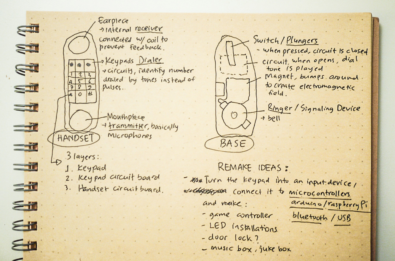
Initially, I wanted to reuse the same old components and try making something new out of it. As far as I can tell, thing that is reusable enough was probably the Keypad. I was thinking that the Keypad can be connected to a Microcontroller/Arduino board/Raspberry Pi or even Bluetooth/USB port, and then become an input device that you can attach to some other things. So I started sketching the other possible form and I came up with these two ideas:
- Making a LED board game, or
- A Jukebox Player

My research took a really long time and after all, it was a dead-end. The challenge I faced was too big and too many to handle in such short period, like: "How do I connect the Keypad to the microcontrollers?", "Which wire cable connects to which part of this thing?", How do I program this thing to connect them to the LED board?", and so on.. and so on.
I know that is unfinished project, I realized that I'm running out of time and it's impossible to learn & implement all of this in 1 day. So hopefully when I'm armed with enough knowledge about physical computing I can continue on this left-over project.
Cheers!